Documentation
Introduction
The plugin is used for scattering large amounts of objects over an area according to predetermined parameters. There is always one target object, and the scatter target area is determined by a texture. If you wish to scatter over multiple objects, you must add a new NeatScatter object for each target in the scene. The scattering is generated in groups. Each group can have different parameters and different models. The groups are generated sequentially, one after another, and the new models are placed in empty spaces without colliding with previous groups. After the completion of the scattering, the user can delete parts of it and regenerate the scattering in the empty space. The scattering can also be converted to a single mesh or to individual instances. Therefore, it can be used, among else, with Modifiers or other native tools just like any other 3DS Max object. You can also choose to scatter procedural objects, particle sources or lights, which do not have a geometry and specify different objects as their collision mesh.
Installation
The installer will guide you through the installation process. You will be asked to specify a path for your 3DS Max installation, so that the plugin can be copied into the Plugins directory. Alternatively, you can install the plugin .dlo file in a separate folder, and load it from 3DS Max yourself. You then also choose where to install the plugin data. This is where all the configurations, icons, and models will be saved, and you can extend them or modify them within some limits. You can also install the V-Ray extension for plugin rendering in V-Ray. In the end, if you are using a commercial version, you will also have to provide the license code. We also recommend you create a Desktop shortcut for the installation directory, so you can easily access it to add new models or configuration files. After the installation, you can start 3DS Max and start using NeatScatter.
Adding plugin into scene
First you need to add the NeatScatter object into the scene. The NeatScatter object is created by CLICK+DRAG, and there is a 2D icon to show where the NeatScatter object has been added. This icon is used for scatter interaction – you select the scatter object in the scene by clicking on the icon. The icon stays where you initially place it, and marks the object’s pivot. If you want to move the icon, move the pivot position.
Selecting the Target
Before scattering, you have to select the target mesh. Click on the Select Target button and then click on any object in the 3D Viewport. The target has to be an object convertible to a triangle mesh, otherwise it will be ignored.
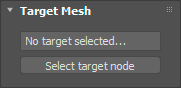
The text field in the Target Mesh tab is filled with the target object name. If the target node is deleted, the NeatScatter automatically changes its target mesh to none, and the generation cannot proceed.
Setting the Parameters
Before you can generate the scattering, you must set up the parameters. The main parameters of the scattering are the following:
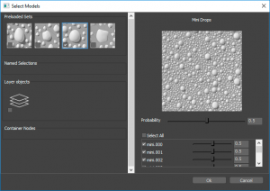
Models Selection:
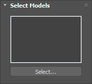
Models to be scattered can be selected from prepared models loaded in the application with the plugin, or any other model from the scene, which can be converted to triangle mesh. All these models appear in the selection dialog automatically. Alternatively, you can also scatter objects that are inconvertible to triangle mesh, if there is another Node in the scene with the same name, but with a convertible “_nscollision” suffix. Said objects also appear in the list – the originals, not the “_nscollision”. When starting the scattering, you must check the Use collision objects checkbox, otherwise said models will be omitted. Models are organized in Sets – in the selection dialog Sets are automatically added for each layer, container or named selection in the scene, with all the models already being added to the Set. You can therefore easily create your own Set by creating a new layer or named selection and adding objects therein. In the dialog, you can select which Sets are going to be used for scattering by checking their checkboxes. When clicking on the Set icon, at the right part of the screen appears a probability slider to specify the probability of selecting this Set during the distribution process. Also, there appears a list with all the models in this Set. You can then specify particular models, and their probability of selection when this Set is being used.
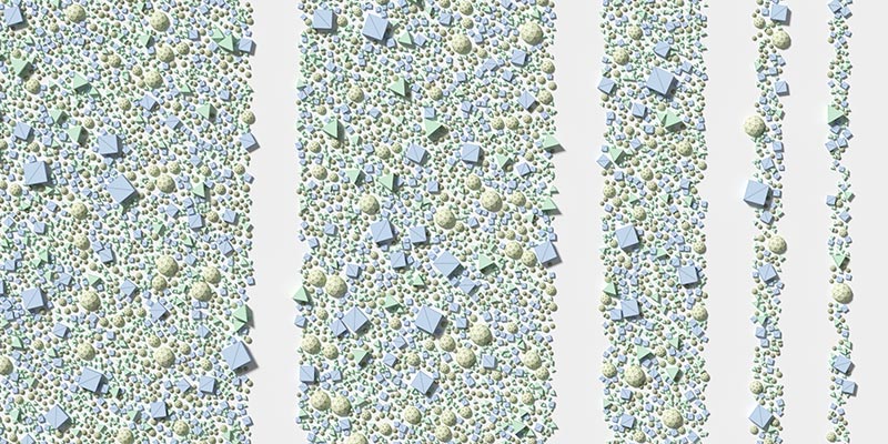
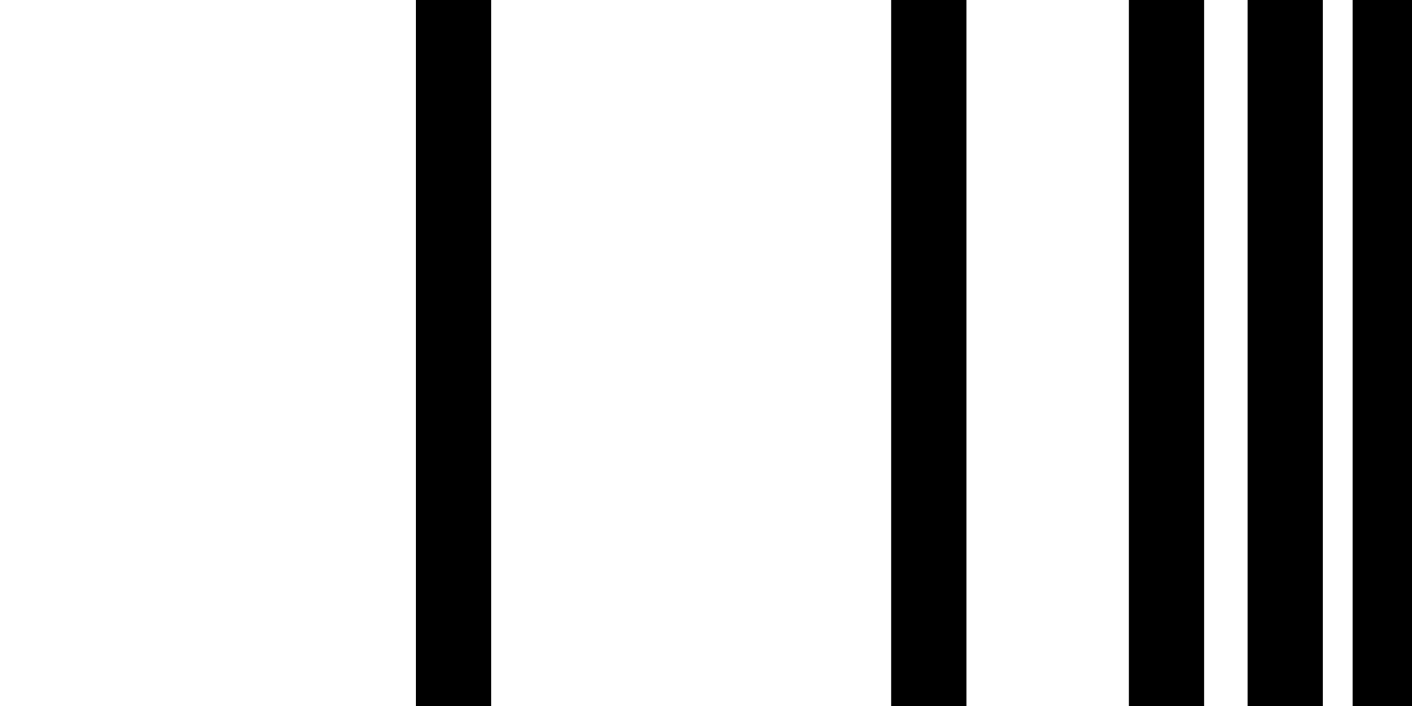
Distribution Mask:
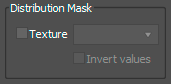
Scatter is always random over the entire area of the target object. You can specify a bitmap texture to work as a Distribution Mask. Algorithm then reads the color value at a given point, as a greyscale value, ranging from 0.0 to 1.0, and uses this value as a probability to determine if a model should be placed at said point. Areas with a value of 0.0 will therefore end up empty, areas with a value of 0.5 half-empty etc.
Model Scale:
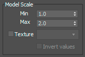
This specifies how much will the scattered object be scaled. It is a range, and the actual scale is randomly selected between the minimum and maximum values. Alternatively, you can use a bitmap texture, where the greyscale color value represents the actual scale: 0.0 is the value of the minimum scale, 1.0 the maximum scale. Values in between are used for interpolation
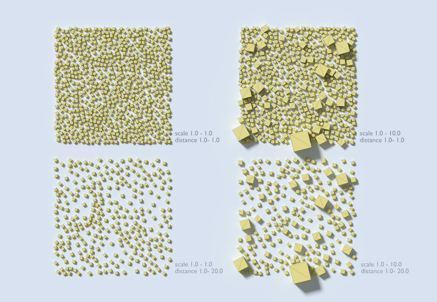
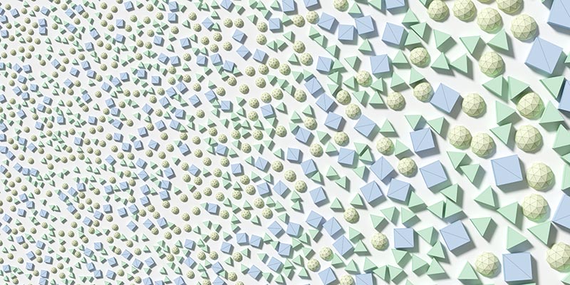

Distance between Models:
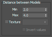
This sets the minimum distance between the models. The algorithm attempts to reach the minimum, placing one sample after another, but usually the models end up being a little farther apart, depending on how well the models fit. The distribution works randomly, so some models placed close to each other can delineate an area where no further models will fit. However, the distance will never be less than the minimum and the samples will not overlap. The distance can also be a range. For each placed model, the algorithm randomly selects a value from the range, and assigns it to the model. Any subsequent model cannot be placed closer to this model than the chosen distance. You can also guide the distance by bitmap texture: a value of 0.0 means the minimum of the distance range will be assigned to placed models whereas a value of 1.0 the maximum. The algorithm uses two ways for computing the distance between two objects – user can select which one they prefer in the Generation parameters tab
-
Sphere Approximation: The algorithm computes the bounding sphere for each scattered model and the distance between the models is calculated as the distance between their bounding spheres.
-
Convex hull: The algorithm computes convex hulls of scattered models and the distance is calculated as the distance between the hulls. This produces a more accurate representation but the distribution can be more time consuming.
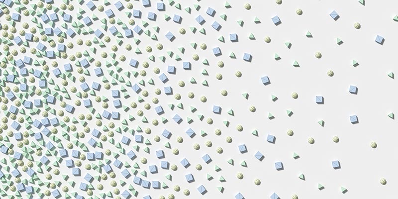
Different Collision Mesh:
When setting up the minimum distance, you can also indicate to use a different collision mesh for any of the models to be used in the distance calculations (this is a global setting in the Generate parameters, near the Generate button – but it will only be used for models which have the collision mesh object present). Your collision mesh can be smaller or larger than the actual object, to create various effects (lightly overlapping objects when the collision mesh is smaller…). It is also recommended to create a simple geometry collision mesh for highly complex models. After the scattering is completed, the real original objects are rendered – the collision objects are used only to compute the distance. To use a different collision mesh than the scattered object, add a new object into the scene, with the same name as the object you want to scatter and add the suffix “_nscollision”. For example, if you want to scatter an object named “Sphere”, its collision object must be named “Sphere_nscollision”. Then just check the checkbox to use collision objects in the Generate tab and the mesh will be automatically detected. An object that does not have a collision mesh specified will use itself for collisions, so you do not have to create collision meshes for all objects you want to scatter.
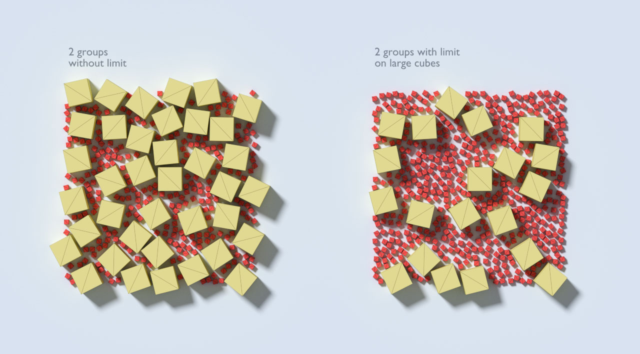
Limit:
![]()
You can limit the number of models scattered in a given group. The limit serves as an upper ceiling – it might not be reached (if only fewer models fit), but it is guaranteed the number of models will not exceed the limit.
Random Seed:
![]()
You can control the random seed used in the generation to randomize the output. Different random seeds result in different results. At the same time, if all parameters are identical (including target model), the same random seed results in exactly the same distribution every time the user generates the distribution.
Model Orientation:
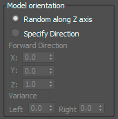
This determines the scattered models transformation matrix. The models are always oriented so that the up-axis is aligned with surface normal at the point they are placed. This means they are always on the surface, facing outward from the target object. Then, if you select Random along Z axis, it means that the model is also rotated randomly along its up-axis for extra variance. Models are placed facing outward, but then rotate randomly around their Z-axis. All models have the same orientation, their Z-axis is aligned with target normal, and their forward axis was specified. The teapots are not perfectly aligned, there is some variance in both directions.
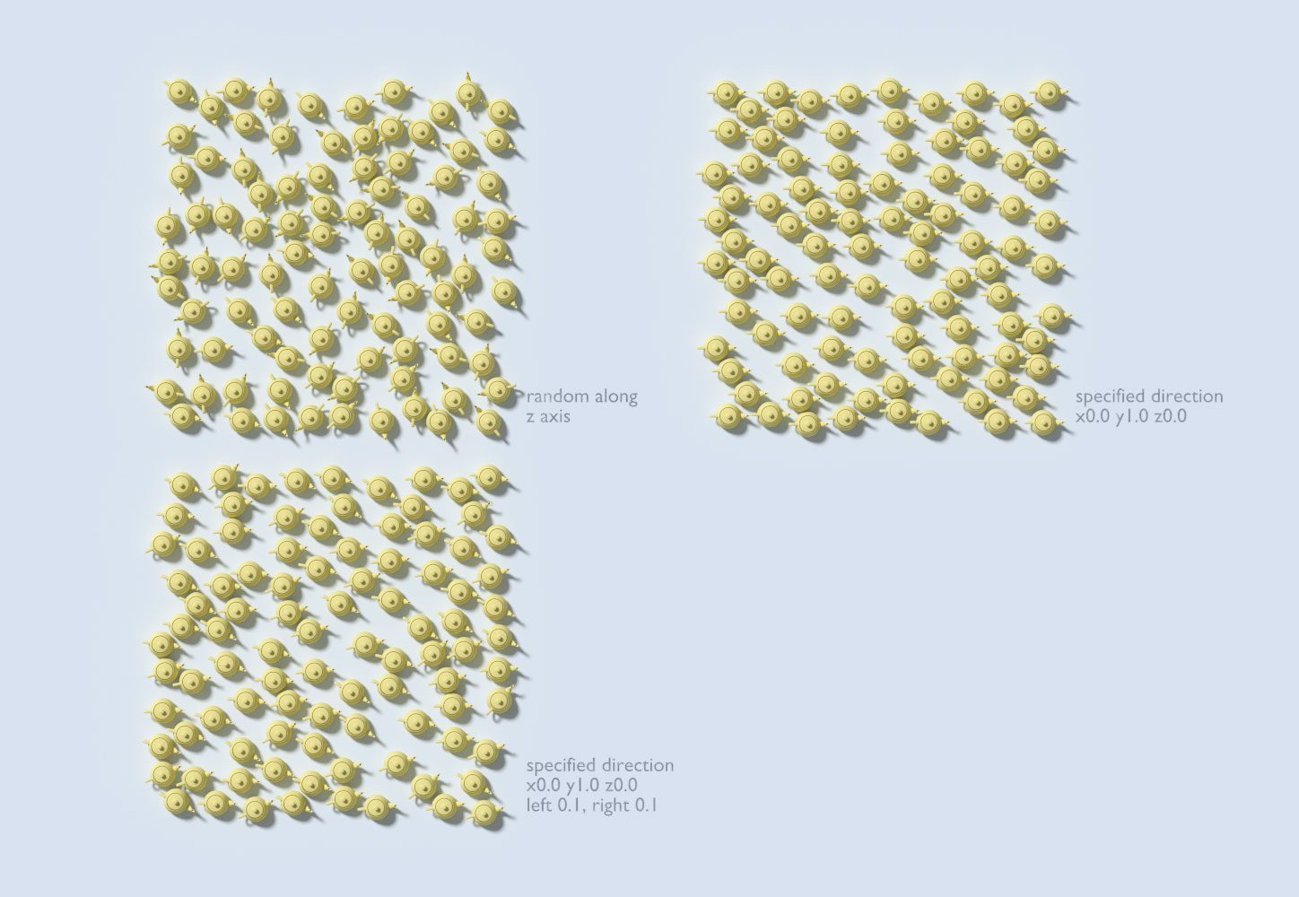
For extra variability, you can also specify a variance of the rotation for left and right of the forward direction. For example when you would like to simulate rain drops in a windy environment, drops flow mostly down, but are not perfectly aligned, they slightly rotate depending on the wind direction. This is the end of the parameters section.
Working with Groups
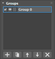
The actual distribution of the models works in groups. Each group can have different parameters and different models. The algorithm then generates group after group, from top to bottom and each group is aware of the previously generated models. The minimum distance is always valid exclusively for the currently generated group. This means that if the previous group had larger distance between the models (therefore with large gaps between them), the next group can fill said gaps – because the minimum distance can be smaller. You can create new groups, alter their arrangement, or copy the settings from one group to a new one and only modify some of the parameters. There is a checkbox for each group. This instructs the algorithm, whether a group should be used during the generation. If the group is not checked, it will be ignored. There is also a button with Lock icon on it. This is used when modifying an existing scattering and you want to lock a group which you like while changing other groups. When a group is locked its models will remain unchanged until the user clicks the Generate button again. Even if said group is not selected, the models will not get deleted or altered in any way. Other groups will ignore said placed models as if priorly generated. Following the generation, all models are displayed in viewport. However, the user can hide some groups from the viewport by clicking on the Eye icon. Only groups with the Eye icon turned on are displayed.
Generation Setup
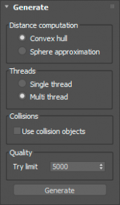
As mentioned above, each group has its own distribution parameters. However, there are some common parameters, that are used for all groups during generation. The first parameter is Distance Computation. To compute a distance between two objects, we either create bounding spheres for the objects and compute distance as the distance between said spheres or we compute convex hull representations and compute the distance between the convex hulls. This is a more accurate representation for uneven shapes, however the computation can be more time consuming.
Another parameter is multi-threading. The scattering can be computed on multiple threads. This results in faster computation, however it requires some approximations. For example, the Limit option only serves as an upper ceiling and it may not be reached even if there is sufficient space in the area. This is because each thread needs to estimate its own sub-limit – in the event that certain threads work faster, we do not want some areas to be more densely populated than others. Single-thread on the other hand distributes all models consecutively, so the area is guaranteed to be evenly populated and if the limit can be reached, it will be reached.
Before starting the algorithm, you can select to Use collision objects. This is explained above, in the parameters section, under distance computation, but a short summary: When this checkbox is checked, for each scattered model, the algorithm attempts to search for a collision object – an object in the scene with the same name, but with the “_nscollision” suffix. (e.g. if your scatter node is named “Tree”, it will search for “Tree_nscollision”). If it finds such an object, then all the collisions and distance computations used in the algorithm are done on the collision mesh, instead of the original object. For models which do not have such a node (there is no “_nscollision” node), the algorithm simply uses their own mesh – so you can select only some collision meshes for some nodes, you do not have to create them all.
Try limit is the last parameter you need to set up before the generation. As mentioned above, samples are placed randomly, and often the algorithm picks a location, where the sample cannot fit. This is considered an “unsuccessful attempt” to place a sample. As the algorithm keeps running, it records how many times it failed, and restarts the counter when it eventually finds an appropriate place. Try limit is how many unsuccessful attempts the algorithm makes before completely giving up and stopping the computations. The larger this number is, the “harder” will the algorithm try, but the computation will also last longer. However, if this number is too small, it will result in very poor results.
Instance Representation
After all the models have been scattered, the NeatScatter maintains the references to the original objects. Therefore, if the user changes anything on the original scene object, said changes will also be displayed on the scattered instances.This includes the change of geometry, material or the application of a modifier. The change of transformation matrix is not included, because the matrix constitutes part of the node not the object, and each instance has a transformation matrix of its own.
Rendering
Currently, the plugin can be rendered in 3DS Max built-in renderers and V-Ray. In V-Ray, it uses instances, so memory usage should not increase too much during rendering. However, some of the built-in renderers internally create a single mesh from all the instances, so for a large count of scattered models, this can cause a memory overflow.
Display in the Viewport
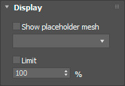
You can change the view mode of the scattered models in 3DS Max Viewport. Instead of the actual meshes, you can choose to display a placeholder box or a plane at each location. Furtermore, you can limit the ratio of displayed models, as the viewport is significantly slowed down by large amount of models. If you expect large amounts of scattered models, it is recommended to setup these settings before the generation, because the GUI can become non-responsive if it attempts to display too many models in the viewport after the completion of the generation.
Statistics
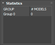
The user can see how many models were generated in each group in the Statistics tab.
Modify Group Distribution
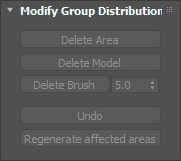
After the generation is completed, you may want to modify the resulting scattering. To change the distribution, you can delete some parts of it and regenerate the scattering on the affected triangles (the ones containing deleted samples). There are three tools for model deletion. All of them work in the viewport, on models visible in the viewport. Therefore, if you wish to delete models from a specific group only, you can hide all the other groups (by un-checking the Eye icon in the group list).
- First, you can start deleting rectangular areas by clicking the Delete Area button. This switches the NeatScatter into the delete mode and you can click and drag a rectangle over the viewport to delete models within that rectangle. You can click and drag multiple times and if you mis-click, you can use the Undo button underneath. You can exit this mode by either clicking the Finish button or with a right mouse click.
- You can also click on the Delete Model button and then select individual models in the viewport. Again, you exit the delete mode by either clicking the Finish button or with a right mouse click.
- The last option is to click the Delete by Brush button. Thereupon, click and hold the mouse pointer in the viewport and drag it across the scattered models. This deletes all models in the mouse path as if you were using a brush. The brush width must be set in advance.
This method can be very slow if a large amount of models are displayed in the viewport, because the viewport needs to be redrawn after every brush move, so it is recommended to brush slowly. For all modes, there is also the Undo button to undo the last selection. Undo functions only while the user is in delete mode. After pressing Generate, or Regenerate Area, all previous changes are confirmed and cannot be reversed. Every group that has been affected by the erasing also automatically becomes “Frozen” (see chapter Groups above). Therefore the user can also choose to regenerate the entire distribution (pressing Generate) and add new groups to fill the new gaps. New models will be scattered over the entire area again (not just the triangles affected by deletions), however the Frozen groups will remain unchanged. Another option is to click Regenerate Area. It works exactly like generate – you also need to create new groups to fill the gaps – but the new samples will only be placed in triangles where at least one sample was deleted from. Untouched areas remain unchanged.
Convert / Export
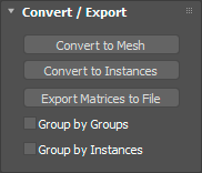
When you are satisfied with the generated scattering, you can convert the entire NeatScatter object to a simple Mesh. This is not recommended for large amounts of models. You can select Group by Groups to create one mesh for each group. Only the visible groups (those that have the Eye icon on) will be exported. Or you can select Group by Instances to create one mesh for each scattered model. Therefore, all instances of one model will be placed in one mesh. If you have selected both, it creates one mesh for each model type for each group.
The NeatScatter can also convert all scattered instances into native 3DS Max instances. However, the process can take a longer time, because each instance is a new scene node and adding a node into the scene is not fast. The objects themselves or their meshes are not copied, just instanced, nevertheless a large amount of nodes can cause 3DS Max to slow down excessively, therefore it is recommended to export groups successively (hiding the other groups during the conversion) if your scattering is very large (> 20000 instances). Again, during the conversion, you can select the grouping, but this only affects how the placement of the instanced nodes in the layer structures.
You can also export the scattering as a separate text file. This can be used for further processing in a different program, or just for exporting the scattering information in a minimal form. Group by Groups or Group by Instances setting has no effect on result, text file will contain all instances together with corresponding groups. Each generated instance is on one line. Each line looks like this:
“group_name“;“path_to_model_file";"model_name";1;0;0;0;0;1;0;0;0;0;1;0;0;0;0;1
- Group name to which instance belongs.
- Path to .max file the model was taken from. This is empty if model from scene was used.
- Model name.
- 12 numbers – transformation matrix in row form.
This raw data can be used in another 3d package that supports scripting. If you have placed all referenced objects in scene you might use the data like in following pseudocode:
with open(instances.txt) as file
    list = file.readlines()

container = new EmptyObject()

for line in list
    group, path, name, 3dsMaxMatrix = line.split()
    matrix = 3dsMaxMatrix.convert()
    baseObject = scene.getObject(name)
    instance = baseObject.makeInstance()
    instance.setMatrix(matrix)
    instance.setParent(container)